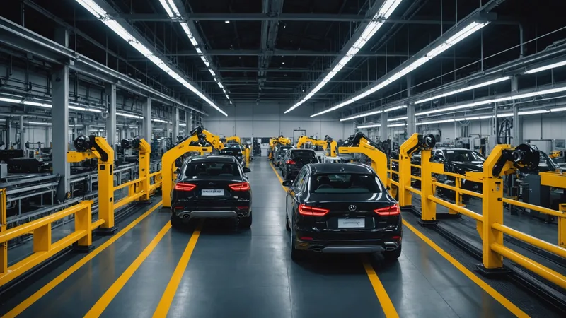
The conversation around AI visual inspection in automotive manufacturing has shifted. Two years ago, the pitch was mostly theoretical: "imagine if you could inspect every part." Now, enough installations are running in production that the honest answer to "does it work?" has detail and nuance to it. It works very well in some cases, adequately in others, and it's genuinely not the right tool for a few scenarios that plants keep trying to apply it to.
This article covers what we've learned from deploying camera-based AI inspection on stamped metal lines, primarily in tier-1 and tier-2 automotive suppliers in Michigan and Ohio.
Where camera AI consistently outperforms statistical sampling
The strongest case for AI visual inspection is in high-volume stamped metal: body panels, structural brackets, floor pans. These parts run at cycle times between 3 and 12 seconds per part, they have a well-defined defect vocabulary (surface cracks, edge tears, surface voids, hole punch misalignment), and the cost of a defect reaching the body shop or final assembly line is disproportionately high relative to the part cost.
Statistical sampling on a press line running 800 parts per shift gives you maybe 40 to 80 parts inspected. If your defect rate is 0.3%, you'll see one defective part every two or three shifts of inspection. That's not enough resolution to detect die wear, coolant contamination events, or material lot shifts before they generate a batch of scrap. Camera inspection at every part changes that resolution immediately.
The detection performance for stamped metal surface defects is good. For cracks, voids, and edge tears with any meaningful visual signature (0.5mm or wider), false negative rates are below 1.5% in our deployments. False positives run between 0.5% and 1.2% depending on part geometry complexity and lighting consistency.
Where AI inspection is adequate but needs configuration care
Dimensional verification via camera is accurate for feature presence (hole exists, chamfer present, slot location correct) but less reliable for tight tolerance dimensional measurement. If your specification is "hole present, diameter approximately 8mm, within 3mm of nominal position," camera is fine. If your specification is "hole center within 0.15mm of datum," you're in CMM territory. Camera-based dimensional checks work best as a 100% screening pass that flags gross outliers for CMM verification, not as a replacement for contact measurement.
Surface contamination detection works but requires consistent lighting. Lubricant contamination on a stamped part photographed under inconsistent ambient light will generate false positives in a way that a fixed illumination setup mostly avoids. The configuration work to get this right is worth doing, but it's real work.
Where camera inspection is not the right tool
Internal defects (subsurface cracks, internal porosity in castings, weld fusion quality below the surface) are not visible to a camera. This sounds obvious, but we see RFQs regularly that ask for AI camera inspection on casting surface finish when the actual customer concern is internal porosity. The camera will tell you the surface finish is acceptable. It has nothing to say about what's inside the casting.
Parts with extremely high geometric complexity and multiple surfaces that can't be covered by a fixed camera array without rotation are candidates for robotic cell inspection, not inline camera inspection. A fixed camera array can cover 80% of a complex bracket's surfaces reliably; getting to 99% requires either part rotation or multiple camera positions that may not fit the line layout.
What to verify before signing a purchase order
Ask your vendor for detection rate numbers specific to your defect classes and part geometry, not generic marketing figures. A 99.2% detection rate on flat sheet metal surface cracks may be accurate. That number is meaningless for bent tubular assemblies with complex weld seams.
Run a shadow mode period before going live. Shadow mode means the camera runs and classifies parts in parallel with your existing inspection process, but does not trigger any reject mechanism. This lets you compare the camera's classification to your human inspectors' decisions over a statistically meaningful sample before you trust the system to run autonomously. A vendor that discourages shadow mode is a red flag.
Verify the MES integration design before deployment, not after. If the defect events don't flow cleanly into your production order quality records in SAP or Plex, the data is technically correct but practically useless for your QA team.
Practical deployment timeline
A well-scoped single-line deployment on a stamped metal part runs 4 to 7 days from hardware arrival to shadow mode start. That includes camera mounting, edge unit installation, initial model training on a good-part image set, and basic MES integration. Shadow mode runs for two to four weeks before live inspection starts. Full autonomous operation, including model confidence refinement, stabilizes at 4 to 6 weeks post-deployment.
The plants that have the smoothest deployments are the ones where the quality engineering team owns the process from day one, not IT. IT needs to be involved for network access and MES integration credentials, but the camera placement, lighting setup, and threshold configuration are engineering decisions that work best when QA owns them directly.